Sunday, January 30, 2011

Power Distribution and Wiring


We are now into our 23rd day of the build season and with one robot drivetrain completed, today's efforts concentrated on several other areas.


The frame for robot #2 continued with drilling axle spacers and bracing. 


Work on the wire routing and crimping continued on robot #2 between the power distribution
board and the controllers.


Construction of the fabric covers for the foam bumpers began today with many yards of fabric cut to size by two of our talented parent mentors. 


Two red and two blue bumper covers must be sewn for each of the four sides of the robot frame (one set for each team).

Saturday, January 29, 2011

FIRST PROTO END EFFECTOR

After a very long day, we had some exciting progress...


Robot frame #1 was completely reinforced with cross-braces and mounting brackets for the drivetrain. 


Per the exploded part drawings that were generated from our CAD team, the gearbox assembly and drivetrain components were also assembled and installed into frame #1.  We are calling this years design, the "tri-power", as 3 motors on each side of the chassis power the drivetrain system.


As expected, more drilling and tapping was needed for some drivetrain attachments as well. Many design tweaks are made 'on the fly'!


Our first end effector prototype was ready for a test at 10 PM and the excitement was high!  


Step one was to mount our roller mockup to last years robot chassis and test the mechanisms that will rotate toward each other to pick up the game peices, and away to release them. The candy cane striped material on the rollers is a urethane belt which is quite tacky and yeilds itself well to this capture application.


Step two was to try out the pick up and release functions with the game peices (inflated circle, square and triangles in the shape of the FIRST Robotics Logo).

One of our Lead Mentors is trying on the game peice for size in this photo!


After careful tryout
and discussion, it 
was decided that
the rollers should be adjusted inboard to prevent
entrapment and
enhance the release of
the game peice.


Step three was to mount the roller mockup lower on the chassis to simulate its designed playing position in which it will pick up game pieces from the floor.


Finally, at 10:19 PM, a successful capture and release of the gamepeice! A simple solution to an interesting challenge and a beautiful end to a very long day! 

Friday, January 28, 2011

SPARKS and SWITCH BRACKETS


The sparks were flying tonight.  We trimmed motor shafts to fit our robot drive system and it was quite the show!


If for some reason you are unable to view the video clip, the photo on the upper right gives a sample view of the show!


We had a very slim crowd of 2 students and 5 mentors tonight, so we concentrated on switch bracket fabrication and used the bandsaw, drillpress and pressbrake equipment to create the parts.  The drawings were created from our design data in the Autodesk Inventor CAD software.


Last evening, there were more students and they learned how to drill and tap screw threads into aluminum blocks to provide attachment features on various parts of the robot. It was a challenge tapping the threads by hand, but the students learned alot from the experience.


And then of course, there's just plain fun!!!


Wednesday, January 26, 2011

Water Jet Parts


Tonight we received all the parts that were sent out to be cut with waterjet technology.  Most of the gears and bracketry were designed in the blank for 4x6 ft aluminum sheet stock and cut straight from the CAD data. The parts were separated out of the pattern and then carefully sanded on the edges.


The students then drilled the 1/4 inch holes to a slightly larger diameter (17/64ths). They did a great job considering how many holes required drilling! The waterjet holes just gave them a good start!  :-) 


Filing and sanding the teeth on small gears is a tedious job so there was plenty of work for everyone and the students had fun!


We had the pleasure of a visit with a photojournalist from the Flint Journal tonight and the programming team had a chance to demonstrate some navigation techniques with last year's robot chassis.


One of our Lady Martian drivers demonstrated the controls to the photojournalist and  explained how they affect the motion of the robot.


There is always work to be accomplished and we so much appreciate the assistance of our parent mentors in help with the many technical as well as administrative tasks of the team.  There is a job for everyone and we could not do this without your valued contributions! 

               Thank you, Mentor Parents! 


Tuesday, January 25, 2011

Ribbet, Ribbet, RIVETS...


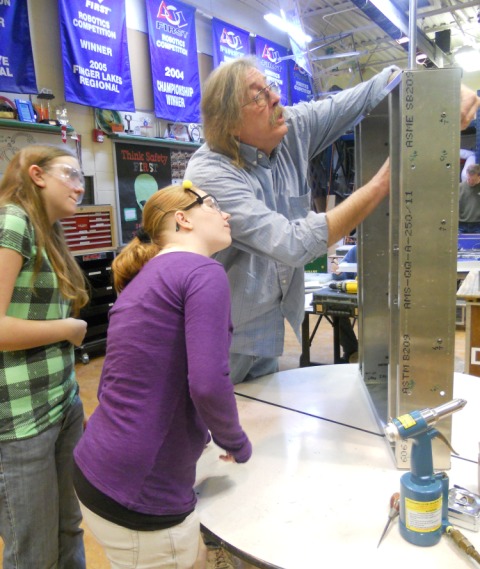
Constructing the bottom of the robot frame was the focus of one of several build teams tonight.


Rivets holes were measured, drilled and popped into place with a pneumatic rivet tool. 


A center punch is usually used to make an indentation in the metal, but a scratch awl works just as well to make the divots that enable accurate drilling of  attachment holes in the frame!  :-)


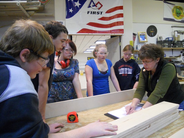
A second build team continued to work on the electrical and controls layout in a plywood mockup.  This  simulates the packaging space in the aluminum frame and allows simultaneous fabrication and construction under the direction of talented electrical mentors.


The multiple aluminum supports for the turret that will be mounted to the frame were also cut on a bandsaw and drilled with one of several drill presses in the build room.


Many of these supports have angled sides that were a bit difficult to cut.


Several of our team members also helped out making the Martian Team Buttons that are customarily given away at competitions as souveniers and traded with other teams for trinkets and collectibles.


Finally, and perhaps of top importance, students began to practice navigation techniques for driving the robot, using the XBox Kinect system.  We intend to ultimately attach it to the robot vision system so navigating will simulate human anatomical movements of the driver. 


It may be prohibited this year in competition, but it will evolve and we want to be ready!

Monday, January 24, 2011

LOGO MOTION

Yesterday was another long day with finishing up the first chassis frame and assembling the aluminum peices.  Some of the students also began constructing the templates for mounting the controllers on a lexan plate. We also learned how to use a press brake.


For those of you who do not know the object of this year's challenge, I have posted this link to an overview video simulation of the robot game. It is called "LogoMotion" as you can see from the picture on the right. We have our work cut out for us, but so much fun ahead!! 

Enjoy....
http://www.youtube.com/watch?v=DTJOXTIaa9g&feature=player_detailpage

Saturday, January 22, 2011

Chassis Holes and Bumpers


Awesome days flow into amazing nights in the Robotics room!  We had nearly a full crew for most of the day and well into the evening, accomplishing many critical tasks.

Cutting the aluminum bracketry for the chassis is always a painstaking job - especially with a bandsaw, but team members pitched in and finished the task with only some slight mis-cuts or sizing errors.


Sanding the same thin aluminum stock to finished dimensions for the bracketry is tedious, but many hands make light work.


Earlier in the afternoon, a test mockup of the electrical, drivetrain and battery were placed into a sample chassis frame to get a visual idea of how things are fitting together, helping to layout the electrical components for the robot controls.


Maintaining the build room equipment and machinery is crutial to productivity. If a piece of equipment is not well maintained, it can mean hours of delays, when a simple 'tune-up' or a few minutes of maintenance can keep a tool performing well when it is needed most! 


'Holes, holes, holes and of course, more holes' was the key phrase tonight.  We performed what seemed to be endless drilling of holes in all shapes and sizes - most were for the attachment of axles, motors, and bumpers.  Everyone got a turn using one of the three drill presses we have in the build room. We were able to finish up the attachment holes in the chassis frame and brackets.


Finally, last but not least, building the wooden bumper supports that will attach the foam 'Noodle' shock absorbers to the robot frame provided an excellent oportunity to learn about various wood fasteners and the bumper applications in the rules for competition.